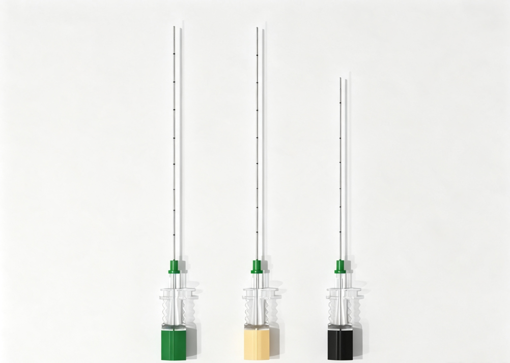
Quick answer: A nerve block needle tip can disappear during ultrasound-guided procedures because of specular reflection, limited surface enhancement, imaging settings, or needle alignment. A smooth metal needle reflects ultrasound energy away from the transducer when the insertion angle becomes steep. An echogenic needle with circumferential 360° laser-engraved features can improve visibility across different rotational orientations and a broader range of insertion angles.
You can see the shaft clearly. Then you advance two centimetres, the angle steepens, and the tip is gone. You are injecting toward a structure you can no longer confirm, and the safe response — stop, reposition, re-image — costs time you may not have.
This is one of the common frustrations in ultrasound-guided regional anaesthesia. However, poor needle-tip visibility does not always mean the needle itself is the problem. It can result from four independent factors: reflection geometry, surface design, ultrasound machine settings, and needle handling technique.
Understanding which factor is responsible helps determine whether a different nerve block needle will improve visibility or whether the solution lies in adjusting the ultrasound system or insertion technique.
Why Does a Nerve Block Needle Tip Disappear at Steep Angles?
Before choosing an echogenic needle, it is important to understand how ultrasound interacts with a metal cannula and why visibility changes as the needle advances.
Cause 1: The Geometry of Specular Reflection
A smooth steel cannula behaves like a mirror. When the ultrasound beam strikes it perpendicularly, the echo returns to the transducer and the needle appears bright. As the angle between the beam and the needle deviates from perpendicular, the reflected energy is deflected away from the transducer.
At an insertion angle of around 60–70° relative to the beam — which can occur during deep plexus approaches, paramedian techniques, and procedures involving difficult surface anatomy — relatively little reflected energy may return to the transducer. The needle has not changed. The geometry has.
This explains why a standard nerve block needle may appear clearly during a superficial, shallow-angle block but become difficult to identify during a deeper approach. It also explains why echogenicity claims based only on 40° product photographs provide limited information about performance at steeper angles.
Key point: A needle's ultrasound visibility depends not only on its material but also on the direction of the reflected sound. A smooth surface may return a strong echo at one angle and a weak echo at another.
Cause 2: The Surface Is Enhanced on Only One Side
Some echogenic needle designs place their reflection features on a single face or within a narrow band. This arrangement can work when the enhanced surface is oriented toward the ultrasound beam. However, rotating the needle to redirect the bevel may turn the enhanced face away from the transducer.
In clinical practice, the needle may be rotated to orient the bevel, steer around a structure, or redirect the tip. With a single-face pattern, visibility can fluctuate as the needle is adjusted. Operators may interpret this as inconsistent echogenicity when the enhancement pattern is simply facing the wrong direction.
A 360° circumferential engraving pattern is designed to reduce this rotational dependency. ShineArk's AN-N series uses a 4×4 engraved array distributed around the tip. Because the features are arranged around the circumference, some portion of the pattern can face the ultrasound beam at different rotational orientations.
This design approach is particularly relevant when comparing ultrasound-visible nerve block needles for procedures that require frequent needle rotation and directional adjustment.
Cause 3: Ultrasound Machine Settings and Probe Handling
Before attributing poor echogenic needle visibility to the needle, check the ultrasound settings and probe position. Several adjustments may improve the image without changing the device.
Beam steering
Many modern ultrasound systems allow the beam to be steered, changing its effective angle of incidence without moving the probe. Steering the beam toward the needle path may help recover a tip that has become difficult to see. Availability and effectiveness depend on the ultrasound system and transducer.
Focus and depth
Set the focal zone near the target depth. A needle at 4 cm imaged with the focus at 1 cm may appear blurred regardless of its surface design. Adjust the depth so the region of interest occupies an appropriate portion of the screen.
Frequency
Higher frequencies generally provide better spatial resolution but attenuate more quickly in tissue. For deeper targets, selecting a lower frequency may improve penetration and needle conspicuity, although the final result depends on the patient and imaging conditions.
Gain and time-gain compensation
Excessive gain can produce blooming, making the shaft appear thick while reducing the distinction between the tip and surrounding tissue. Slightly reducing gain may make the tip easier to identify than simply increasing overall image brightness.
Compounding and harmonic settings
Tissue harmonic imaging and spatial compounding can improve tissue contrast but may also soften needle edges in some systems. Try adjusting these functions according to the ultrasound manufacturer's recommendations and observe whether needle-tip definition improves.
Probe pressure and acoustic window
Light probe pressure, sufficient ultrasound gel, and an appropriate probe position can improve acoustic coupling. These factors are particularly important in patients with greater tissue depth, where attenuation may already limit image quality.
Cause 4: Needle Technique — In-Plane Alignment and the Tip-Shaft Problem
The tip is often the most difficult part of a nerve block needle to identify. It presents a smaller reflective area than the shaft and is surrounded by tissue that may have a similar echogenic appearance.
Several technique-related adjustments can help:
Stay strictly in-plane. Out-of-plane drift can shorten the visible needle segment and make the tip harder to distinguish. Even a small degree of misalignment may affect the apparent position of the needle.
Keep the needle as perpendicular to the ultrasound beam as the approach allows. Use beam steering, where available, to improve the relationship between the beam and the needle surface.
Track the tip, not just the shaft. Confirm the tip position at each increment of advancement rather than following the brightest linear structure on the screen.
Consider bevel orientation. Rotating the bevel toward the beam may help with some needle designs. A circumferential echogenic pattern is intended to reduce the visibility penalty associated with rotation.
Consider hydrodissection when clinically appropriate. A small injection of fluid can create an anechoic pocket that outlines the tip and separates it from surrounding fascia.
Advance in small increments. A controlled heel-toe adjustment and careful advancement may help distinguish the moving tip from surrounding tissue artefacts.
Consider a needle guide or fixed-angle approach where appropriate. These may help reduce freehand variability during selected steep trajectories.
How 360° Laser Engraving Improves Echogenic Needle Visibility
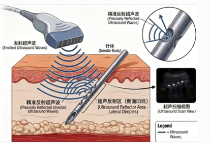
The principle behind 360° laser engraving becomes clearer when the reflection geometry is considered.
A smooth metal shaft tends to reflect ultrasound energy in a particular direction. When a shaft carries a circumferential array of laser-engraved cavities, its surface presents multiple small edges and pockets at different orientations. These features are designed to scatter ultrasound energy rather than rely entirely on a single specular reflection.
ShineArk's AN-N nerve block needle design uses a 4×4 engraved array arranged around the tip. The circumferential arrangement is intended to maintain useful echogenic features when the needle is rotated during insertion.
1. Reduced Dependence on Needle Rotation
With a single-face enhancement pattern, rotating the needle may turn the enhanced surface away from the ultrasound beam. A 360° pattern distributes the features around the cannula circumference, reducing the dependence on a particular rotational orientation.
2. More Consistent Visibility Across Insertion Angles
Multiple surface features provide different orientations for ultrasound interaction. This can help the needle maintain a visible echo over a broader range of angles compared with a smooth cannula. The actual performance still depends on engraving geometry, tissue depth, probe position, and ultrasound settings.
3. Integral Surface Features
Laser-engraved features are formed in the metal surface rather than applied as a separate polymer layer. This avoids the specific coating-delamination concern associated with surface-applied materials. However, engraving depth and edge quality still require appropriate manufacturing control and mechanical verification.
Important limitation: 360° engraving does not make every deep or steep-angle block easy to image. Tissue attenuation, anatomical variation, probe contact, and machine settings continue to affect image quality. The design improves the needle's contribution to visibility; it does not eliminate the underlying imaging limitations.
For a broader comparison of laser-engraved microstructures, corner-cube reflectors, and polymer-based surface treatments, read our article on echogenic needle technologies and how they compare.
Ultrasound Needle Visibility Troubleshooting Guide
The following table connects common imaging observations with possible causes and practical first checks. It can help identify whether the issue is related to reflection geometry, ultrasound settings, needle orientation, or tip design.
| Observation | Possible Cause | First Action to Check |
|---|---|---|
| Shaft bright, tip indistinct | Excessive gain, blooming, or a strong shaft echo | Reduce gain gradually; look for the tip signature rather than the brightest pixel. |
| Whole needle fades as the angle steepens | Specular reflection and limited surface enhancement | Try beam steering, adjust frequency, and reassess needle alignment. |
| Visibility changes when the needle is rotated | Enhancement pattern may be confined to one face | Check needle orientation; consider a circumferential echogenic design for future procurement. |
| Tip visible in near field but lost at depth | Focus and frequency may not match the target depth | Move the focal zone toward the target and reassess the frequency band. |
| Needle visible in phantom but poorly visible in a patient | Tissue attenuation, interfaces, and probe contact differences | Improve the acoustic window, use appropriate probe pressure and gel, and reassess the imaging conditions. |
| Intermittent dropout during advancement | Possible out-of-plane drift or changing beam alignment | Reassess in-plane alignment and advance in controlled increments. |
| Tip looks blurred but shaft remains sharp | Distal tip geometry or enhancement pattern may be insufficiently defined | Ask the supplier for the distal-pattern specification and tip-visibility test data. |
How to Evaluate an Echogenic Nerve Block Needle Before Buying
Product photographs and general claims about ultrasound visibility are not enough to compare different echogenic needle designs. A more useful evaluation uses consistent imaging conditions and tests the factors that affect real-world needle-tip identification.
A basic bench comparison can include the following steps:
Prepare a tissue-mimicking phantom. Use a suitable phantom with a fascia-like layer rather than relying only on water. A phantom provides a more representative environment for comparing ultrasound needle visibility.
Standardise the imaging conditions. At a fixed depth and gain, image each candidate needle at 30°, 45°, 60°, and 70°. Keep the probe, transducer, and other relevant settings consistent.
Test rotational orientation. Rotate each needle in 45° increments at 60° and 70°. Observe whether the tip remains identifiable as the needle orientation changes.
Evaluate tip identification. Ask three blinded clinicians to mark the tip position and measure the error against a reference point. This helps distinguish shaft brightness from actual tip-localisation performance.
Repeat after insertion cycles. Pass the needle through the phantom fascia layer ten times and re-image it under the same conditions. Compare the results before and after insertion.
A needle that maintains a recognisable tip signature at 70° across different rotational orientations demonstrates a different performance profile from one that is only clearly visible at 40°. The protocol should be documented consistently so that results can be compared between products.
For a more detailed bench-testing procedure, see our guide to how to test needle echogenicity.
How to Choose Ultrasound Visible Nerve Block Needles
When comparing ultrasound-visible nerve block needles, procurement teams and healthcare professionals should look beyond a general claim of enhanced visibility. The relevant design and verification details include:
Enhancement mechanism: Determine whether the echogenic features are laser-engraved, grooved, formed as corner-cube reflectors, or created using a coating or surface treatment.
Surface coverage: Check whether the enhancement is arranged around the full circumference or concentrated on one side of the cannula.
Distal tip design: Review the location and length of the enhanced area, together with the bevel and back-bevel configuration.
Angle and rotation testing: Request imaging evidence at multiple insertion angles and rotational orientations, preferably using a tissue-mimicking phantom.
Mechanical verification: For engraved or grooved designs, request relevant bend, strength, or fatigue test information where applicable.
Material and coating information: Confirm cannula material and, where a coating is used, request appropriate adhesion, particulate, and biocompatibility documentation.
Product specifications: Check available gauges, needle lengths, tip configurations, packaging, sterilisation, and applicable regulatory documentation.
For B2B sourcing, these details should be considered alongside the manufacturer's quality management system, production capability, documentation, and ability to support consistent product supply.
The Short Version: What to Check When a Needle Tip Disappears
If an echogenic nerve block needle tip disappears at a steep angle, check three areas in this order:
Ultrasound settings: Review beam steering, focus, depth, gain, and frequency.
Needle technique: Check in-plane alignment, probe contact, bevel orientation, and controlled advancement. Consider hydrodissection when clinically appropriate.
Needle design: Evaluate circumferential echogenic enhancement, distal tip pattern, and whether the surface features are integral to the cannula or applied as a coating.
Only the third area necessarily requires a product change. It is worth checking the first two before concluding that the needle is responsible.
ShineArk AN-N: 360° Laser-Engraved Nerve Block Needle Design
ShineArk's AN-N nerve block needles use a patented 360° imaging reflection design (Chinese invention patent ZL 2019 1 1149952.9), featuring a 4×4 engraved array around the tip. The design uses a 304 medical stainless steel cannula and combines the circumferential enhancement pattern with a short bevel and bilateral back bevel.
According to the supplied product specifications, the AN-N range includes 20G–25G gauges and 50–150 mm needle lengths. For product evaluation, buyers can request detailed specifications, steep-angle imaging information, and samples for their own bench testing.
Looking for Ultrasound Visible Nerve Block Needles?
Explore ShineArk's AN-N echogenic nerve block needle range with a 360° laser-engraved micro-array design. Contact our team for product specifications, technical documentation, evaluation samples, and OEM/ODM sourcing requirements.
Explore AN-N Nerve Block NeedlesContact ShineArk for Product DetailsFrequently Asked Questions
Why can I see the needle shaft but not the tip?
The tip presents a smaller reflective area than the shaft and sits against surrounding tissue with a potentially similar echogenic appearance. Excessive gain can make the shaft appear brighter while blurring the tip. Reducing gain and looking for the tip signature may help more than simply increasing image brightness.
Does a steeper angle always mean worse echogenic needle visibility?
Not necessarily for every needle design, but a smooth needle generally becomes more difficult to image as its surface orientation moves away from the favourable reflection angle. Circumferential surface features are designed to reduce this dependence, although actual performance varies with the needle, tissue, probe, and ultrasound settings.
Can I improve nerve block needle visibility without changing the needle?
Often, yes. Beam steering, focal zone placement, frequency selection, gain adjustment, in-plane alignment, and probe handling can all affect needle visibility. Hydrodissection may also help outline the tip when clinically appropriate. Check the imaging setup and technique before concluding that the needle must be replaced.
Is an echogenic needle worth it for superficial nerve blocks?
The benefit may be less noticeable in shallow approaches where the reflection geometry is already favourable. Enhanced needle designs may be more relevant in deeper or steeper approaches, difficult anatomical conditions, and training environments where clear tip identification is important.
Do coating-based echogenic needles lose visibility over time?
Coating adhesion and abrasion resistance are important considerations because the coating is applied on top of the metal surface. Engraved or grooved features are integral to the cannula and do not present the same coating-delamination mechanism. Buyers should request appropriate adhesion, particulate, and durability test information for coated products.
Intended for healthcare professionals only. This article describes ultrasound imaging physics and medical device design and is not clinical guidance.